Content
In addition to discovering new physics through the analysis of collision data in the LHC, another crucial aspect is the construction of colliders and detectors. Without innovative and reliable equipment, how can we draw meaningful conclusions from our experiments?
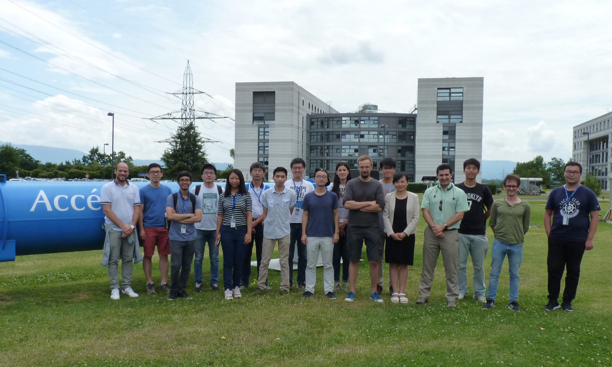
Our team is involved in the development of the Trigger Data Serializer (TDS), a chip used in the muon spectrometer of the ATLAS detector. For readers who are not familiar with ATLAS, please read this concise and engaging introduction.
What is TDS?
That’s a rather lengthy story.
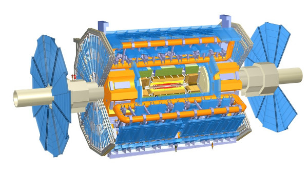
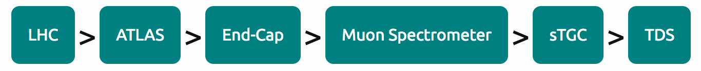
The ATLAS detector, shown as a circular disk, consists of two components: the Barrel (a cylindrical curved surface) and the End-Cap (left and right circular planes). As these components have distinct physical characteristics, specific particle detectors are designed for each one.
A significant portion of the End-Cap is dedicated to muon detection. One of the detectors used is the small-strip Thin Gap Chamber (sTGC), which serves as a primary trigger detector for muons. Each sTGC is accompanied by multiple chips called TDCs – the chips our team is currently working on. The role of the TDC is to process trigger data for the sTGC and serialize it for transmission.
Why is muon detection crucial with sTGC?
The study of the Higgs boson in the LHC is perhaps the most famous experiment in the world. You might read this page describing our work on the Higgs, which offers insights into this field. Tracking the particles produced in the events is key to reconstructing the Higgs boson. Muons are among these particles and play an essential role in event reconstruction.
However, tracking muons turns out to be relatively challenging. Most protons, neutrons, and photons are stopped by the inner calorimeters of ATLAS, but muons manage to escape. To determine the momentum of these muons, the engineers of ATLAS employ a clever trick: they build a strong magnetic field around ATLAS using a superconductor, which bends the trajectory of the muons. By knowing the radius of the trajectory, physicists can calculate the momentum.
Now, how do we determine the radius? That is where the muon spectrometer and the sTGC come into play.
The Role of TDS in sTGC
The sTGC consists of multiple layers, and the muon’s trajectory is identified by its intersection with each layer. However, there are numerous uninteresting signals from the wires in the sTGC, which ATLAS cannot handle efficiently. To tackle this issue, “pads” and “strips” are implemented to record only the interesting events. Another chip receives data from these “pads” and “strips” and determines if the event is significant, thus reducing the workload for ATLAS.
Nevertheless, the “pads” and “strips” merely produce messy binary patterns. This is where TDS, the chip our team is currently working on, comes in. TDS serializes these patterns into an organized format, ready for analysis.
Since ATLAS contains multiple sTGCs, each with numerous “pads” and “strips,” there are thousands of TDS chips in ATLAS.
Our Work
TDS was designed by the University of Michigan. Our goal is to test the chips to ensure they function as expected within ATLAS.
We perform four types of tests, some of which are too technical to describe in detail here. However, we will discuss the most interesting and important tests below.
Chip Function Test
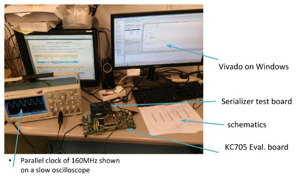
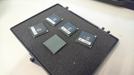
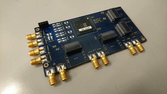
During the design stage, when TDS had not yet been finalized, we worked on a serializer-only prototype chip of TDS. This prototype chip contained only the serializer, a critical component of TDS. As the name suggests, the serializer is responsible for processing signals. The prototype chip alone is not functional, so we embedded it in a test board and connected it to another evaluation kit to provide signals to the test board. Finally, we observed the output on an oscilloscope.
One of the tests we performed is the Bit Error Ratio Test. Essentially, we tested how frequently the chip produced incorrect outputs. We generated signal patterns to be sent to the chip and checked if the output matched our expectations. Obviously, fewer errors indicate better performance.
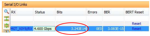
The most crucial columns in the results are “Bits” and “Errors.” The above results indicate that we provided 3.24×10¹⁴ input signals to the chip, and there were zero errors in the output.
Another test is the Eye Diagram, where we’ll skip the technical details and go straight to the interesting result. The Eye Diagram, as the name implies, is a graph that resembles an “eye.” The sharper and more defined the eye appears, the better the chip performs. What do you think of the result?
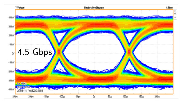
Based on the test results thus far, it seems that the TDS serializer is functional. However, further tests are still pending.
Future Radiation Tests
Testing the prototype chip alone is insufficient. Now that the TDS is ready, we need to verify its full functionality and subject it to more challenging conditions.
In reality, the TDS chip will operate in an environment much harsher than our lab. Within the ATLAS detector, there are numerous energetic particles flying around, some of which could flip a “0” into a “1” in our digital signal! This phenomenon is known as a single event upset.
The TDS is specially designed to withstand these harsh conditions and deliver error-free outputs. To ensure its resilience, we will conduct a radiation test: shooting high-energy protons at the chip with an energy of 100MeV.
We have designed a test board specifically for this radiation test. The board will provide simulated inputs to the TDS chip while monitoring its output. The board, with the TDS chip mounted on it, will be exposed to a proton beam. During this test, the TDS chip must continue functioning despite being bombarded by protons from the beam.